
The light works like the light in a car, it is always ready, I never have to wonder if the batteries are charged, and because the Shimano generator is so efficient, I can have the lights on in flashing mode all the time. At night I switch on steady light and flashing tail lights, so I can see and be seen even when stopped.
On a longer trip I can recharge AA batteries for camera and GPS.
LEDs are very good for my purpose because they optimize the light output for any amperage up to their design limit, so they give very efficient light at slow speeds. Also, the multiple LEDs assure that the generator does not overpower the system. I never have to worry about burned out bulbs.
This light is brighter than a popular Planet Light 2 watt LED bicycle light and lights a larger area at about 8 mph.
A Power graph is shown below.

 The basic LED set up comes from a 68 LED Pailide light that costs under $10. The LEDs are mounted in a printed circuit that is designed to have all the LEDs in a 4 volt parallel circuit. For my use, I only want the LEDs and their printed mounting board. I don't use the switch, most of the case, or the original battery holder.
For the a housing, I use an Energizer Hard Case Flashlight that comes with a clamshell holding 4 AA batteries. The front of the Pailide flashlight shell holds the LEDs and fits nicely over the front of the larger flashlight. I change the contacts on the battery holder so that it becomes a series wiring of the 4 batteries. The switch wires are changed too, in order to match the wiring plan shown below. With the NiMH rechargeable batteries this becomes a nominal 4.8 volts, but actually charges to 5.2 volts typically.

The battery holder for the flashlight is modified to change the batteries to 4 AA in series from the original way that has 2 AA batteries in parallel with 2 AA batteries.

The Shimano Generator is alternating current and designed for 6 volts. I want to divide the LEDs into two circuits that each can run off of one phase of the AC power. I also want to turn the LEDs in to series wiring so that the voltage is doubled from the nominal 3.6 - 4 volts that white LEDs run on.
Since there are many LEDs, I configure the circuit with a separate set of 12 LEDs run by the switched battery pack.
This plan then becomes a double set of 14 LEDs in series with 14 LEDs, and a set of 12 LEDs connected to the switch controlled battery power. This switched battery circuit also runs the flashing tail lights.
The Bridge Rectifier effectively drops the voltage to the proper charging range of the batteries. The batteries act as capacitors for the system. Capacitors could be added on the circuit if desired. I have not found overcharging a problem, so I did not use capacitors on this light. Two more diodes are added between the battery pack and the set of 12 LEDs so that the 4 AA batteries do not overpower the LEDs.
Because the LEDs are Diodes, the AC current will only go through the set of LEDs that has the correct polarity. The two sets of 28 LED are alternately flashing, but you will never notice this as a rider. At slow speeds the flashing will attract the attention of viewers looking at the approaching bicycle.
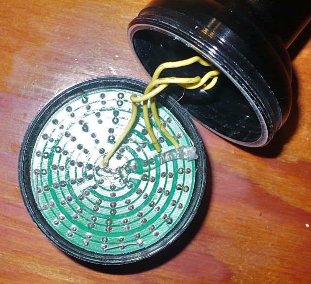
The LED mounting board in the Pailide light can be modified to create a compact system with the desired wiring plan. This requires carefully scratching out some of the connection circuit and adding bridge connections. Soldering and wiring is required. It takes some careful marking and planning to get the system connected, but it is not overly demanding of soldering skills.

The black lines show where I will scratch out the circuit with a razor blade knife. The yellow arrows show the planned new connection bridges. The red and blue lines mark the 12 LED set that will connect to the battery.
The blue dots show where the two AC connections will be.
I do not use any of the original wires, they are too small to hold well after soldering.
I carefully count and follow 14 LEDs, then scrape off the next connection. I then connect the negative end of that set of LEDs to the positive end of the next 14 LEDs. There will be two sets of 14 +14 LEDs. The positive end of one set of 28 LEDs is then connected to the negative end of the other 28 LEDs. One of the two AC wires will connect to one of the two bridge connections, marked by a blue dot. The other AC wire connects to the other bridge connection, also marked by a blue dot.
The mounting case is plastic. I want to make sure that no part of the wiring connects to any part of the bicycle frame. If a metal case were to be used for mounting the system, it is important that it is not grounded to the bicycle frame.
There is room in the flashlight for the AC wires, a bridge rectifier, wires exiting to the taillights, and clips that join to the copper contacts from the switch. Outside the flashlight I use standard 2 pole trailer wiring connectors

This view highlights the connected sets of 14 LEDs.
The yellow highlight is 14 LEDs connected in series with the green highlighted 14 LEDs. When the AC current makes the left blue dot positive then the current flows through these 28 LEDs.
The purple highlight shows 14 LEDs that are connected in series with the Pink highlighted 14 LEDs. When the right side blue dot is positive the current flows through the purple set of LEDs in series with the pink highlighted set of LEDs and through the long yellow bridge arrow to complete the circuit.

The yellow and green set of LEDs are lighted, as viewed from the back side of the circuit board.

The pink and purple sets of LEDs are lighted when the poles reverse.

The battery lights these 12 LEDs when the switch is on.

The light mounted.
Performance:
With batteries at 1.31 Volts per battery and the battery switch off, the following readings were made:
MPH Volts Amps Watts
8 6.8 0.45 3
10 7.2 0.5 3.6
15 7.3 0.52 3.8
20 7.4 0.54 4
At 20 mph the 56 LED will have 0.071 watts per LED. The nominal design output for standard white LEDs is 0.025 Amps at 4.0 Volts = 0.1 watt. At 31 mph the system does not over power the LEDs.
The type of LED in this light probably gives about 70 - 100 lumens per watt, so at 10 mph I would be getting 250 - 350 lumens and the light is covering an ellipse ellipse 6 feet by 15 feet centered 20-30 feet in front of the bicycle. The light is very good for speeds 8 - 12 mph in an urban or rural road environment.
No comments:
Post a Comment